
Milling Technology & Difficult Materials
68° & 70° High-Helix End Mills
How unequal pitch and 40°/42° variable-helix geometry can improve cutting stability when milling titanium alloys, 316 stainless steel and high-temperature alloys.
Geometry Overview
One End Mill, Two Ways to Break the Vibration Cycle
Difficult-to-machine materials place heat, cutting load and vibration into a narrow contact zone. A conventional tool with evenly spaced teeth and one constant helix can reinforce the same vibration pattern every time a cutting edge enters the workpiece. PRONIXT’s 68° and 70° high-helix end mill series combines unequal pitch with variable-helix geometry to interrupt that repeating pattern and support a smoother cut.
The two design features do different jobs. Unequal pitch changes the angular spacing between cutting edges around the tool. Variable helix changes the flute angle along the cutting edges. Used together, they spread cutting forces over different timing intervals instead of allowing every flute to excite the same harmonic frequency.
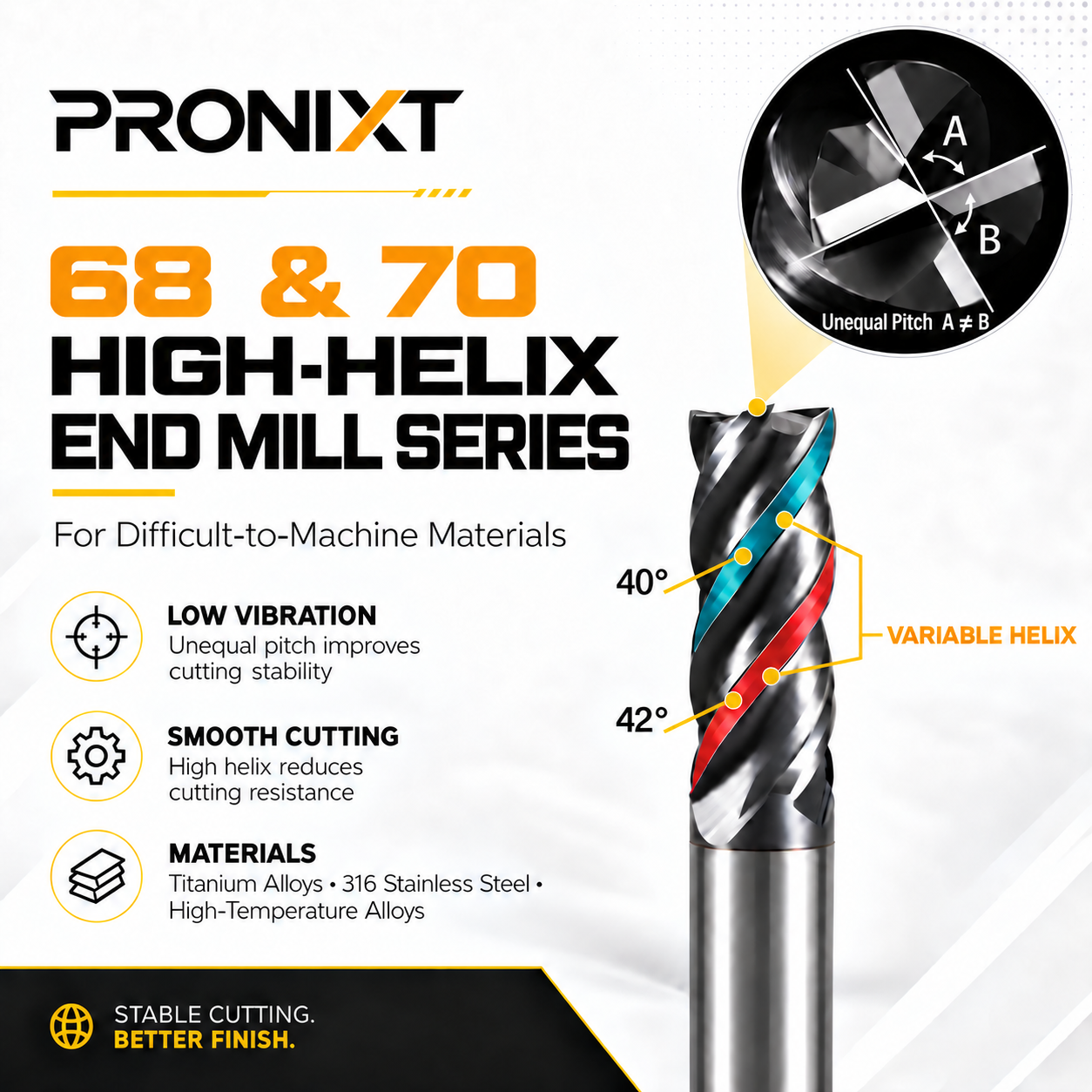
These identify the two PRONIXT high-helix end mill series and their intended application positioning.
These are the paired variable-helix angles shown in the technical illustration. They describe the alternating flute geometry, not the series name.
How the Geometry Works
Why Unequal Pitch and Variable Helix Matter
Unequal Pitch: A ≠ B
When tooth spacing is unequal, the interval between successive cutting-edge engagements changes. This helps break up a single repeating excitation frequency, reducing the tendency for harmonics to build into visible chatter.
Variable Helix: 40°/42°
Different helix angles change how each flute enters and leaves the cut. The alternating geometry distributes the cutting load and can make the transition between flutes feel smoother under stable machining conditions.
High-Helix Shearing Action
A high-helix cutting edge engages the material progressively rather than all at once. This supports smooth shearing and can reduce radial cutting resistance, which is useful when finish quality and wall stability matter.
More Stable Surface Generation
Lower vibration helps the cutting edge follow the programmed path more consistently. The practical result can be fewer chatter marks, a more uniform finish and less need for corrective finishing passes.
Target Applications
Designed for Materials That Concentrate Heat and Cutting Load
Titanium alloys, austenitic stainless steels and heat-resistant alloys behave differently, but they share one practical demand: the cutting process must remain stable. Chatter, rubbing and inconsistent chip thickness quickly turn into heat, edge damage and poor surface quality.
Titanium Alloys
Titanium has low thermal conductivity, so much of the cutting heat remains near the tool edge. Stable engagement, effective coolant delivery and controlled radial width of cut help protect the edge from local heat concentration.
316 Stainless Steel
316 stainless steel is tough, ductile and prone to work hardening when the edge rubs instead of cutting. Maintain a positive chip load, avoid unnecessary dwell and use a rigid setup to keep the cutting action consistent.
High-Temperature Alloys
Nickel-based and other high-temperature alloys retain strength at elevated temperatures and place high stress on the edge. Conservative engagement, reliable coolant and a short tool overhang are essential starting points.
Series Selection
Choosing Between the 68° and 70° Series
The correct choice depends on whether the application needs broader process flexibility or places maximum priority on the final surface. The guidance below describes the intended positioning of the two series; the final tool selection should also consider diameter, flute length, corner form, coating, holder and machine rigidity.
68° Series
A balanced option for applications that need one tool to cover semi-roughing, side milling and finishing. Choose it when stable material removal and a reliable finish are both important.
- Roughing and finishing in one process plan
- General side milling and profiling
- Applications with changing engagement
- Balanced productivity and finish quality
70° Series
A finishing-focused option for lighter engagement where smooth cutting and surface quality take priority. Use it with a rigid holder, controlled runout and a well-supported workpiece.
- Final profiling and finishing passes
- Thin walls or surfaces sensitive to vibration
- Light radial engagement
- Applications where finish is the main target
| Selection factor | 68° series | 70° series |
|---|---|---|
| Primary role | General-purpose high-performance milling | Finish-oriented high-helix milling |
| Typical operation | Semi-roughing, side milling and finishing | Profiling, wall finishing and light finishing passes |
| Main priority | Balance of stability, material removal and finish | Smooth cutting and surface quality |
| Setup requirement | Rigid holder and controlled tool overhang | High rigidity, low runout and especially stable workholding |
Application Guidance
Before Setting Cutting Data
There is no single speed and feed that fits every titanium, stainless or high-temperature-alloy job. Start from the exact tool specification and adjust according to the real setup.
- Keep tool overhang as short as the part permits
- Use a clean, rigid holder with controlled runout
- Confirm radial and axial engagement before setting feed
- Maintain chip load and avoid rubbing or dwelling
- Direct coolant consistently into the cutting zone
- Watch chip form, sound, spindle load and edge wear
- Reduce engagement before simply reducing feed
- Re-tune parameters when holder or overhang changes
Technical Evaluation
Information Needed for a Useful Recommendation
To recommend a suitable 68° or 70° series end mill, PRONIXT needs more than the material family. Send the exact material grade and hardness, tool diameter, flute length, corner requirement, radial and axial depth of cut, toolholder, machine model, coolant method and the current problem you want to solve.
Photos of the setup and an existing tool can also help, but a dimensioned drawing remains the best way to confirm reach, interference and critical geometry. Review the complete PRONIXT Solid Carbide End Mill range before sending your application details. Additional finished tooling examples are available in the PRONIXT Precision Tooling Product Gallery.
Need an End Mill for a Difficult Material?
Send the material grade, tool dimensions, holder, machine model and cutting conditions. PRONIXT can help evaluate the appropriate series and geometry for your application.
PRONIXT provides solid carbide cutting tools, technical support, drawing confirmation and customized tooling solutions for CNC machining applications.