
Collets & Guide Bushes
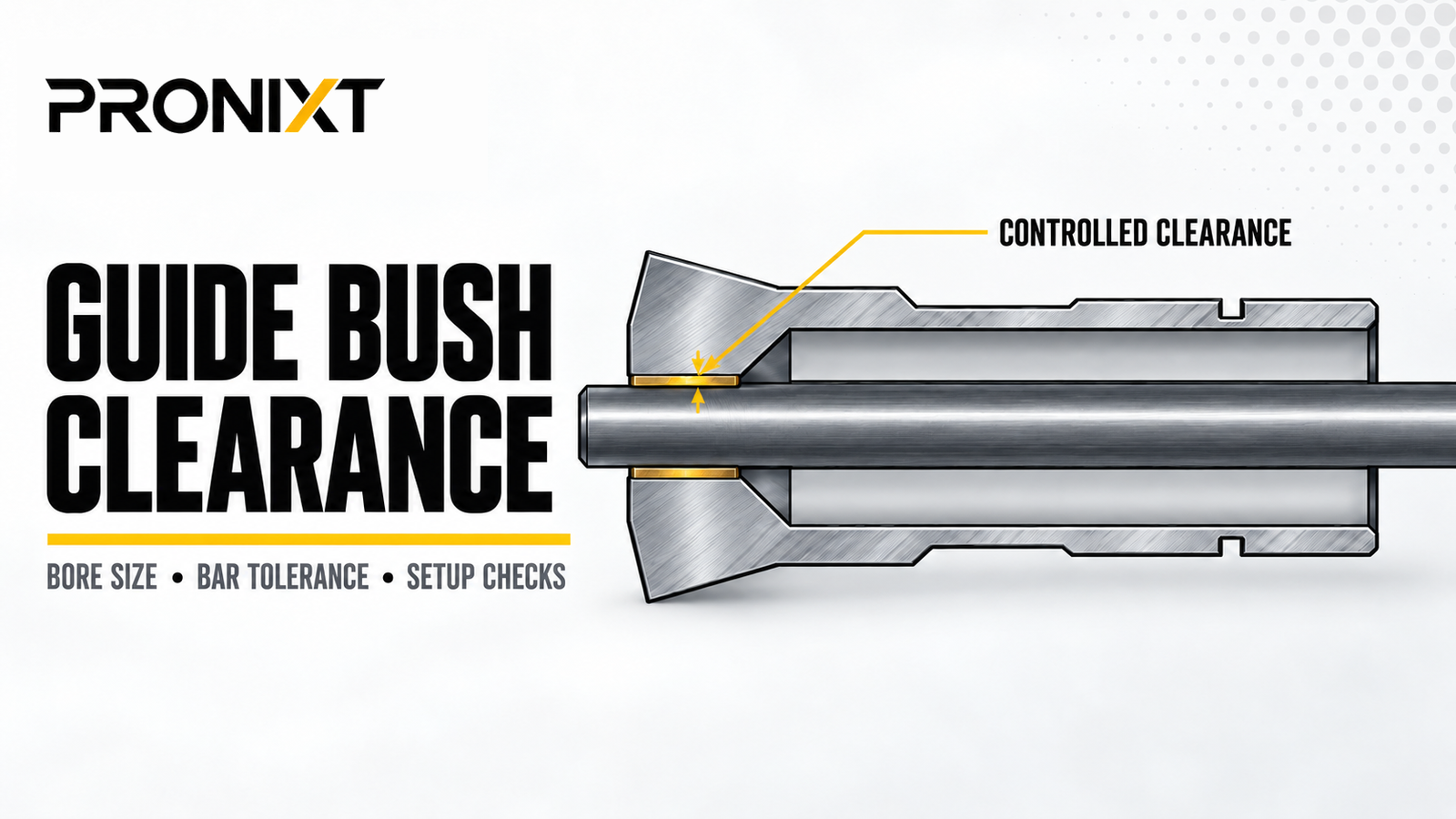
Swiss-Type Lathe Guide Bush Clearance: How to Select the Correct Bore Size
Guide bush clearance must allow the bar to move smoothly while keeping it firmly supported near the cutting zone. The correct setting depends on the actual bar stock, guide bush design, machine condition and machining requirements—not the nominal diameter alone.
Clearance Basics
What Is Guide Bush Clearance?
Guide bush clearance is the controlled space between the workpiece bar and the finished bore of the guide bush. In a Swiss-type lathe, the guide bush supports the bar very close to the cutting tool. The objective is to reduce radial movement and deflection without restricting the bar’s axial feed or rotation.
If the fit is too loose, the guide bush cannot provide stable support. If it is too tight, the bar may bind, overheat, become scratched or feed inconsistently. A reliable setup therefore balances two requirements: free movement and minimum practical play.
Why It Changes
Five Factors That Determine the Required Fit
Actual Bar Diameter
Measure the maximum real diameter, not only the nominal size stated on the material label.
Roundness and Straightness
An out-of-round or bent bar can bind even when one measured diameter appears acceptable.
Surface Condition
Drawn, ground, polished, scaled or coated stock can behave differently inside the guide bush.
Temperature and Lubrication
Heat, cutting oil, contamination and trapped chips can change how freely the bar moves during production.
Application Requirements
Part length, cutting load, tolerance, finish and spindle speed determine how much support is needed.
Guide Bush System
Fixed, rotary and synchronous systems have different installation and adjustment procedures.
Stock Inspection
Measure the Bar Before Selecting the Bore
A guide bush ordered only from a nominal size can be correct on paper and still fail on the machine. Check several bars from the intended production lot. Measure at multiple positions along each bar and rotate the micrometer orientation to detect diameter variation and out-of-roundness.
The largest measured condition is especially important because it represents the point most likely to bind. Also inspect straightness, local damage, burrs, seams, scale and changes between material batches. A guide bush cannot compensate for severely inconsistent stock.
| Bar condition | What to check | Why it affects clearance |
|---|---|---|
| Ground or polished bar | Diameter consistency, finish and cleanliness | Uniform stock generally allows more controlled support, provided it remains straight and clean. |
| Drawn bar | Size variation, seams, lobing and straightness | Variation along the bar may require additional working allowance or improved stock preparation. |
| Hexagon or profile stock | Across-flats size, corner condition, twist and profile consistency | The guide bush bore must match the real profile and orientation requirements, not a round-diameter assumption. |
| Soft or easily marked material | Surface sensitivity, chips, lubrication and bore finish | A rough or contaminated bore can mark the workpiece even when the dimensional fit appears acceptable. |
| Stock from multiple lots | Maximum and minimum diameter for every lot | A setup proven with one batch may bind or lose support when material variation changes. |
Setup Procedure
A Practical Method for Checking Guide Bush Fit
- Confirm the machine and guide bush family. Verify the machine brand, exact model, guide bush type, body dimensions, thread and locating geometry before considering the bore.
- Clean the complete assembly. Remove chips, dirt and damaged material from the guide bush bore, holder and locating surfaces.
- Measure representative production bars. Record maximum and minimum diameters at several positions and orientations, then check straightness and surface condition.
- Set the guide bush according to the machine procedure. Use the machine builder’s recommended installation and adjustment method. Do not force the guide bush tighter to compensate for another setup problem.
- Check movement through the usable bar length. The bar should move smoothly without obvious radial looseness, tight spots, scraping or sudden changes in resistance.
- Run a controlled test. Begin cautiously, allow the machine and cutting oil to approach normal operating condition, and inspect temperature, feed behavior, surface marking and part dimensions.
- Document the approved setup. Record the material lot, actual bar range, guide bush identification and machine adjustment so the result can be repeated.
Troubleshooting
How to Recognize Clearance That Is Too Tight or Too Loose
Possible Signs of Insufficient Clearance
- The bar binds or does not feed consistently
- Local heat develops near the guide bush
- Scratches, scoring or polished bands appear on the stock
- Spindle load or resistance changes during bar movement
- One section of the bar passes while another becomes tight
Possible Signs of Excessive Clearance
- Chatter appears during turning or cutoff
- Part diameter or taper becomes unstable
- Surface finish changes as the cutting load changes
- Long or slender features show increased deflection
- Radial bar movement can be detected at the support point
Material Options
Steel and Carbide-Lined Guide Bushes
Steel Guide Bush
Steel is a practical choice for many standard applications, prototypes and smaller production quantities. Bore finish, heat treatment, geometry and correct adjustment remain essential.
Carbide-Lined Guide Bush
A carbide-lined bore can provide improved wear resistance for suitable production conditions. It does not remove the need for consistent stock, correct clearance, clean lubrication and accurate alignment.
The best option depends on the workpiece material, stock finish, expected quantity, speed, required accuracy and replacement interval. PRONIXT can provide steel or carbide-lined constructions for compatible standard and customized guide bush families.
Ordering Information
What to Provide for a Guide Bush Quotation
| Required information | Recommended details |
|---|---|
| Machine | Brand, complete model, bar capacity and guide bush system |
| Existing guide bush | Model number, engraved marking, drawing or clear photos |
| External geometry | Body diameters, overall length, shoulder, locating angle and thread |
| Bar stock | Material, nominal size, measured size range, tolerance, profile and surface condition |
| Application | Part length, required accuracy, production quantity and known operating issues |
| Construction | Steel or carbide-lined preference, if already determined |
If the original reference number is unknown, start with our Swiss-type lathe collet and guide bush identification guide or compare common families in the PRONIXT model number reference.
Compatibility pages are also available for TSUGAMI, STAR, CITIZEN and TORNOS Swiss-type lathes.
Brand names and machine models are shown for compatibility reference only. PRONIXT is an independent tooling supplier and is not affiliated with the listed machine manufacturers.
Frequently Asked Questions
Guide Bush Clearance FAQ
Can I order the guide bush bore at the nominal bar diameter?
Not safely without checking the real stock. The actual bar may vary in diameter, roundness, straightness and surface condition. Confirm the machine procedure and representative production material first.
Should the bar feel completely tight inside the guide bush?
No. The bar must still rotate and move axially without binding. The goal is minimum practical play with reliable movement under production conditions.
Why does the bar pass when cold but become tight during production?
Temperature, contamination, trapped chips, lubrication and local stock variation can change the working condition. Test the setup as it approaches normal operation and investigate the complete system.
Will a carbide-lined guide bush solve chatter?
Not by itself. Carbide can improve wear resistance, but chatter may also result from excessive clearance, poor stock, tool condition, unsupported length, alignment or cutting parameters.
Can a custom bore be produced from my bar sample?
Yes. A drawing, measured stock data or representative sample can help confirm round, hexagon, square or special-profile requirements. Machine compatibility and external guide bush dimensions must also be verified.
Need a Guide Bush for Your Swiss-Type Lathe?
Send us the machine model, existing guide bush reference, actual bar dimensions, material, required quantity and available photos or drawings. We will review the information for a compatible standard or customized solution.
Leave a Reply